Key Takeaways & Protocol Essentials
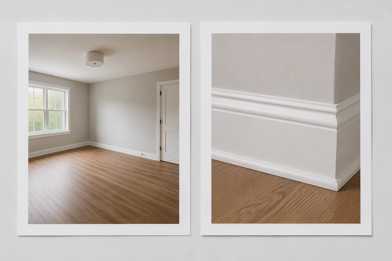
- Never capture a macro damage shot without first anchoring the view in a wide overview frame showing two adjacent reference boundaries.
- Maintain continuous directional orientation across zoom transitions so reviewers can immediately map detail defects to physical assemblies.
- Record transitional medium shots whenever an isolated defect cannot be unambiguously located from the primary room entrance perspective.
The Spatial Continuity Rule: Why Overview Establishes Scope Legitimacy
In property condition assessment and repair scope documentation, isolated close-up photos create cognitive friction for estimators and auditors. An extreme close-up of a cracked ceramic floor tile or charred drywall baseboard reveals the nature of material distress, but fails to convey where that tile sits relative to structural boundaries. Without a broad perspective shot, scope reviewers cannot determine whether a damaged section covers two square feet or an entire floor plan.
Establishing spatial continuity requires a disciplined two-tier photo hierarchy. Every localized material failure must trace directly back to an overview photograph that captures recognizable architectural landmarks—such as window mullions, doorway casings, ceiling transitions, or fixture rough-ins. By anchoring the defect inside the larger room perimeter, the inspector eliminates disputes regarding quantity calculations and boundary assumptions during scope review.
Essential Triad: Overview, Intermediate, and Macro Protocol
Captures full ceiling-to-floor junctions and opposing wall intersections to establish the overall boundary and lighting condition of the workspace.
Bridges the spatial gap between room coordinates and local damage, showing exact distances from permanent architectural fixtures.
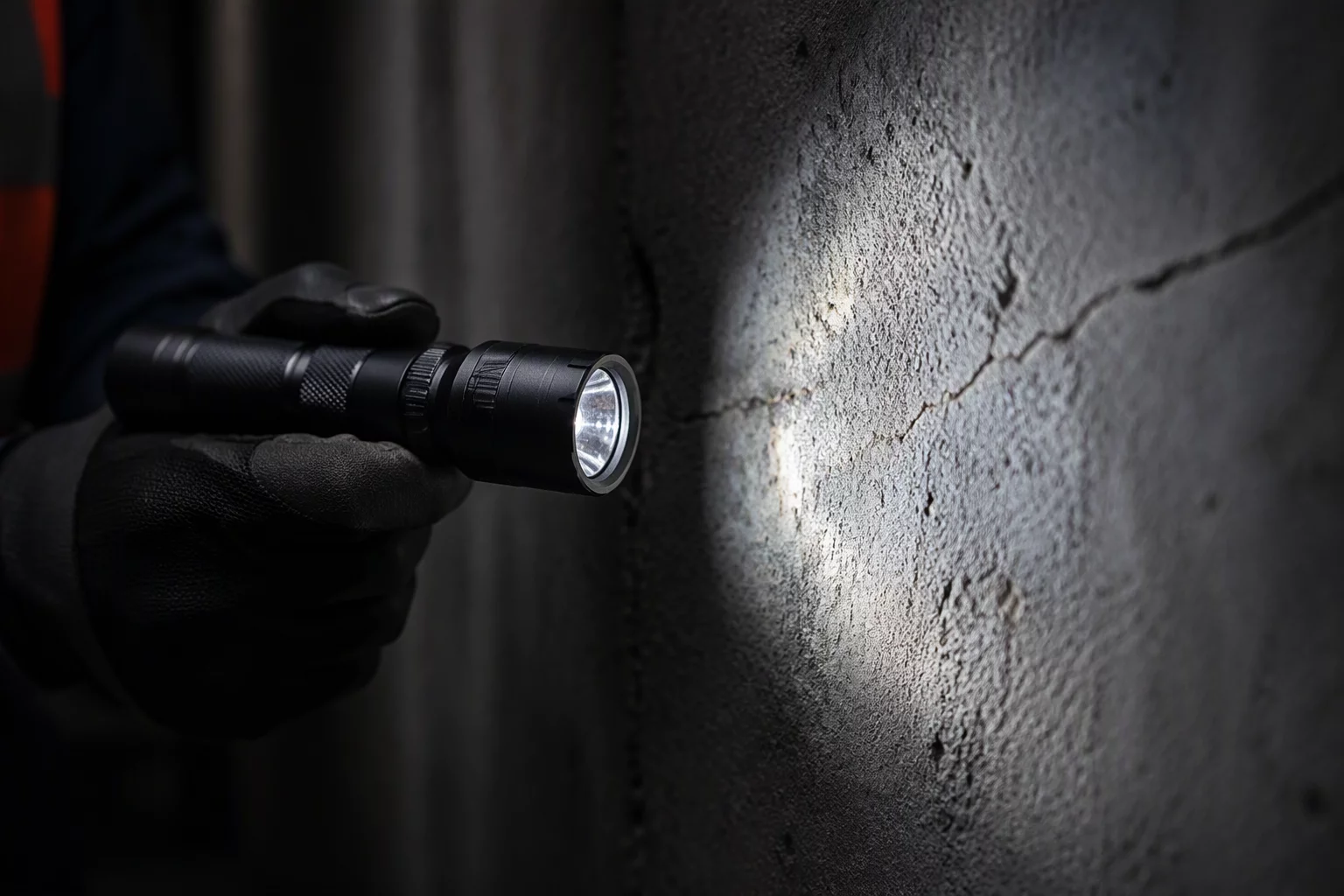
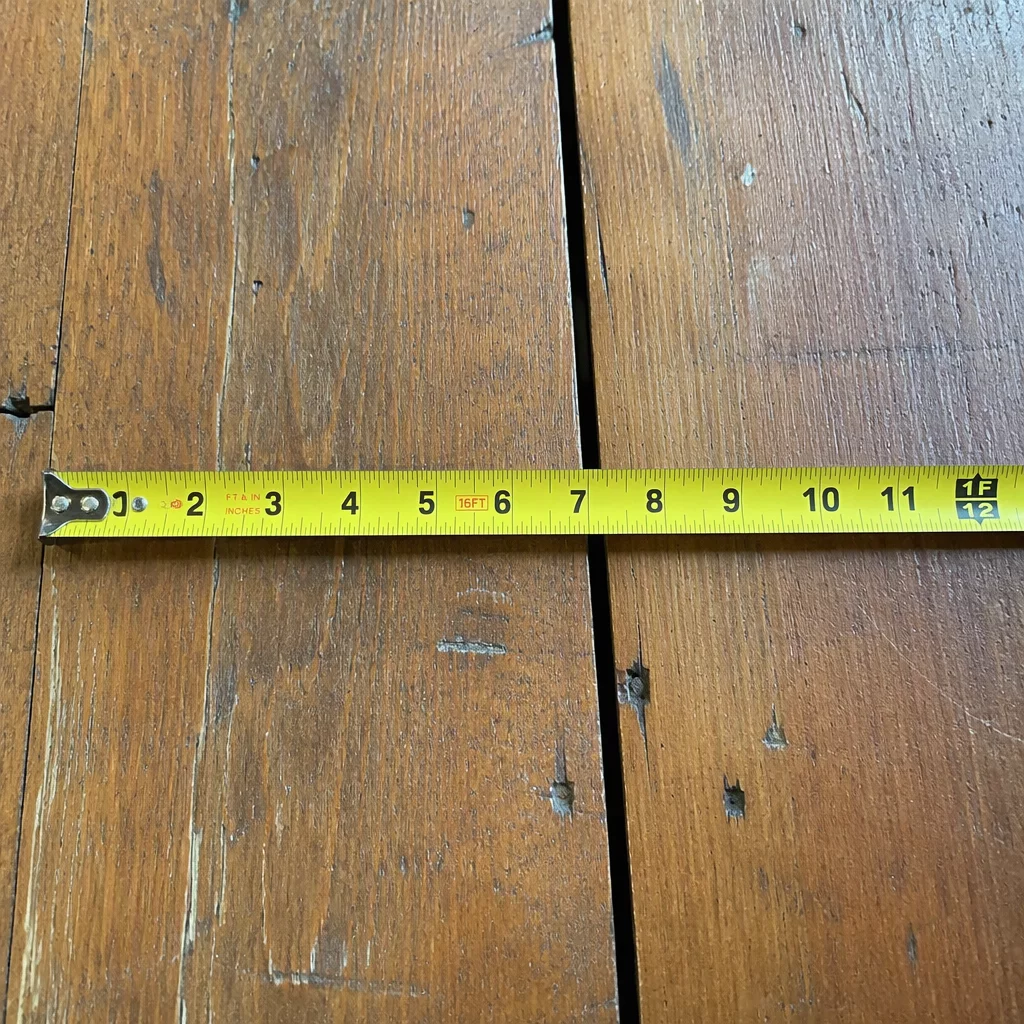
Documents precise failure mechanisms, material thicknesses, surface fractures, and gauge readings with dedicated dimensional indicators.
Linking Material Degradation Directly to Estimate Scope Items
When an estimator constructs line items in a repair scope, each quantity must be defended by visual proof of impact. Overview photos demonstrate why surrounding areas remain unaffected or why continuous floor coverings necessitate complete removal rather than spot repair. Close-up photos, on the other hand, provide evidence of substrate deterioration, delamination, or burn patterns that dictate specific removal and prep procedures.
"A detail photograph proves the damage exists; an overview photograph proves where the repair begins and where the contractor's scope must stop."
Combining both capture tiers in sequential order creates an irrefutable audit trail. Reviewers can cross-examine dimensional callouts in field sketches against overview boundaries, while confirming material grades and specifications through macro lens captures. This methodology reduces supplemental review cycles and safeguards the integrity of final repair estimates.
Technical Comparison & Capture Specifications
| Photographic Tier | Primary Objective & Focal Range | Scope Verification Function |
|---|---|---|
| Wide Overview (24mm–28mm equivalent) | Captures total elevation or full room boundaries including corner junctions | Verifies overall room dimensions, undamaged finishes, and containment lines |
| Intermediate Range (35mm–50mm equivalent) | Frames 4 to 8 feet of contiguous surface surrounding the damaged component | Establishes transition thresholds between affected and sound construction materials |
| Detail / Macro (70mm–105mm or Close Focus) | Isolates specific crack profiles, water stains, mold growth, or brand stamps | Validates material grade, thickness, fastener gauge, and replacement necessity |
Field Inquiries & Observations
No field notes or observations yet. Be the first to leave a comment.
Submit a Field Note or Feedback
Share your site observation insights or questions regarding this methodology.