
Key Takeaways & Protocol Essentials
- Micro-texture and edge-profile photography prevents grade disputes during estimate audits.
- Physical measurements using precision calipers and depth gauges remove guesswork from composite materials.
- Clear substrate documentation establishes proper removal and replacement line-item selections.
Establishing Physical Material Provenance
Accurate material identification forms the bedrock of credible property damage scoping. When adjusters and estimators evaluate repair items, broad descriptions such as 'wood flooring' or 'vinyl siding' often trigger scope disputes. Physical evidence must capture the exact product profile, core composition, backing material, and interlocking mechanism.
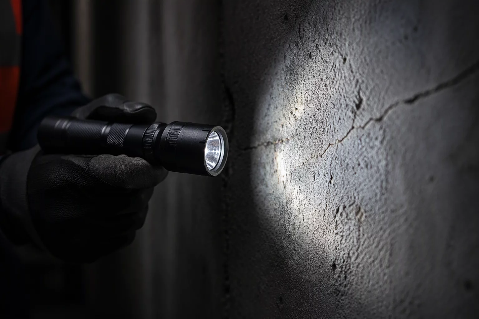
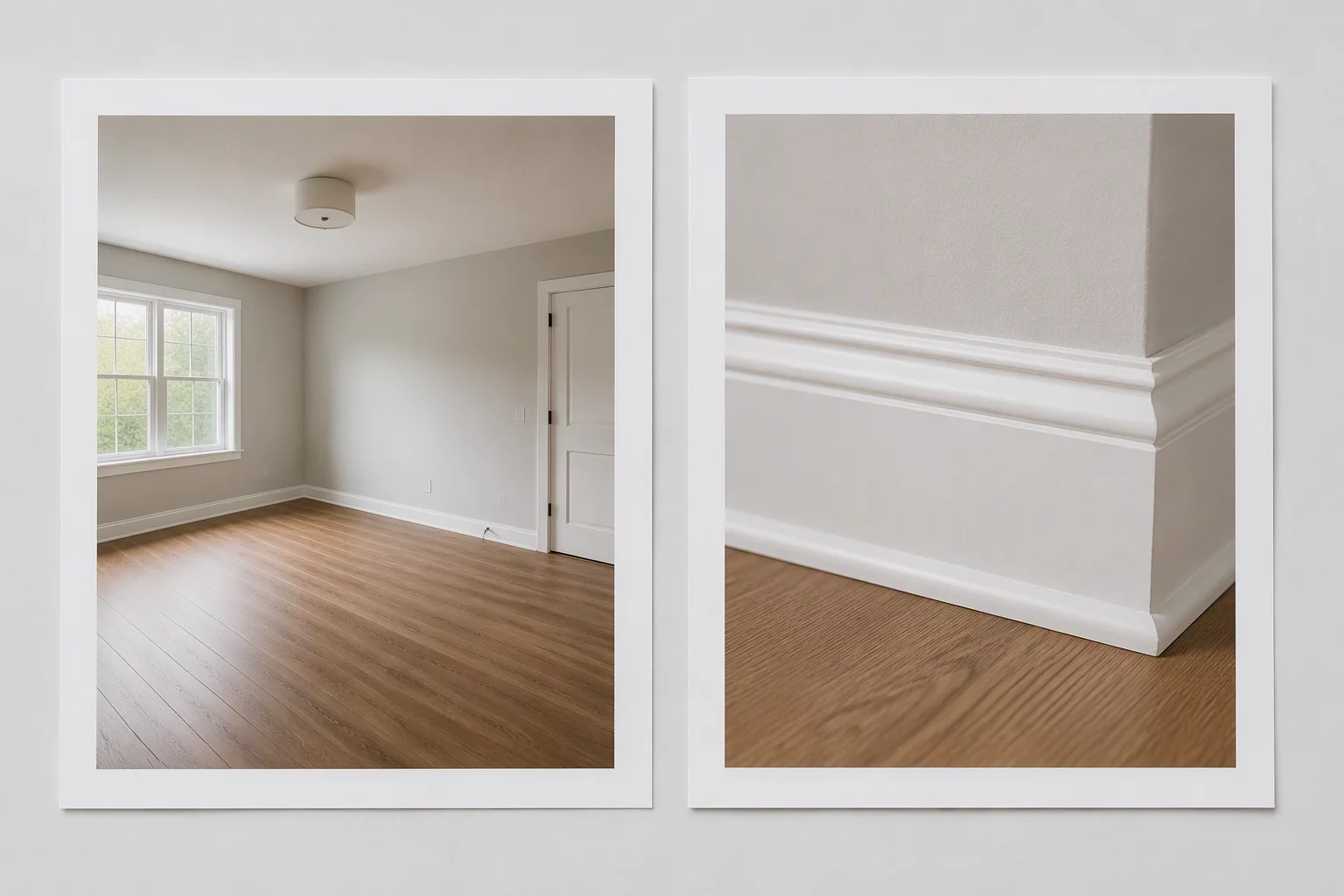
Field inspectors achieve this by pairing wide contextual frames with macro-focus shots. Using scale markers, natural illumination, and angled side lighting exposes subtle grain patterns, factory embossing, and wear layers that differentiate builder-grade materials from premium architectural assemblies.
Core Identification Protocols in the Field
Photograph cut edges at uninstalled ends or damaged seams to expose multilayer construction, engineered veneers, and core density.
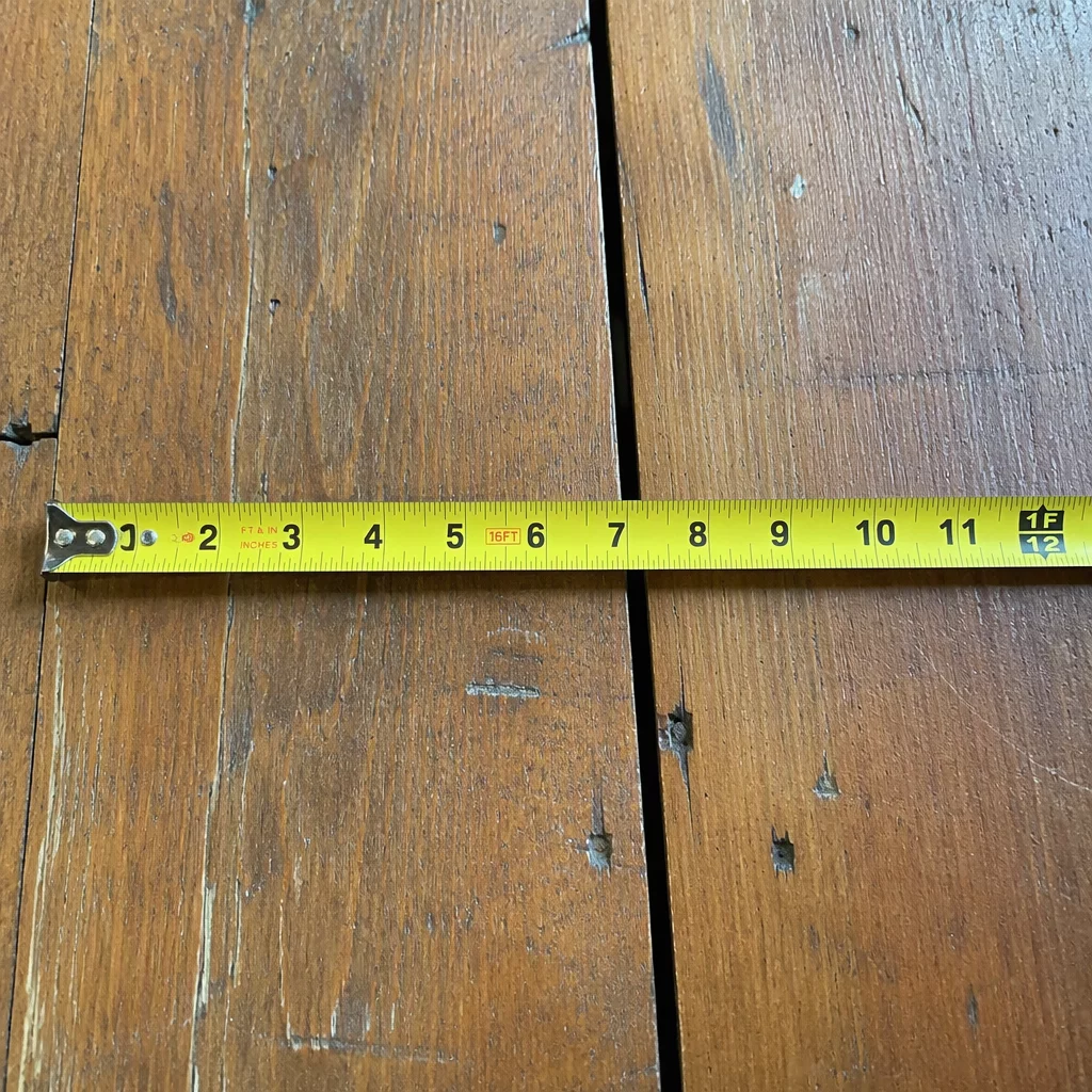
Place precision dial or digital calipers directly across profile lips, sheet thicknesses, and exposure reveals with legible readouts.
Document manufacturer stamps, batch inkjets, fiber backings, and underlayment textures located behind baseboards or fixtures.
Cross-Referencing Substrates to Scope Items
Selecting accurate Xactimate line items requires distinct verification of both visible surfaces and concealed structural layers. For example, mistaking solid hardwood for engineered plank with a 2mm wear layer fundamentally alters drying procedures, sanding allowances, and replacement costs.
"A single macro photograph showing cross-sectional core layers eliminates weeks of supplemental scope negotiations."
When documenting continuous materials across transition thresholds, capture both sides of the junction alongside the underlying subfloor condition. This photographic trail ensures that scope line items reflect actual material specifications rather than speculative assumptions.
Profile and Gauge Field Matrix
| Material Category | Critical Photographic Focus | Scope Alignment Benefit |
|---|---|---|
| Resilient Flooring (LVP / LVT) | Wear layer mil thickness, core type (SPC vs WPC), locking profile | Distinguishes click-lock floating systems from glued vinyl assemblies |
| Exterior Siding & Trim | Reveal exposure height, butt thickness gauge, grain stamp pattern | Prevents incorrect profile matching during partial wall replacements |
| Soft Flooring & Carpet | Tuft bind, face fiber test, primary/secondary backing grid | Justifies fiber quality classification and pad replacement allowances |
Field Inquiries & Observations
Submit a Field Note or Feedback
Share your site observation insights or questions regarding this methodology.