Key Takeaways & Protocol Essentials
- Always capture full-building directional overviews before taking intermediate or close-up damage photographs.
- Establish unambiguous cardinal designations (Front/North, Right/East, Rear/South, Left/West) across all field sketch pages.
- Tie exterior architectural transitions and offsets to physical boundaries to avoid scope omission or overlap disputes.
The Critical Role of Elevation Orientation in Scope Tracing
Exterior inspection documentation often suffers from disoriented detail frames. When a reviewer encounters an isolated photograph showing cracked siding or detached trim, determining the specific wall facet without a wider contextual shot becomes virtually impossible. External elevation context establishes the baseline visual framework, anchoring every localized anomaly to its physical wall plane and structural perimeter.
An effective elevation sequence begins at the primary property approach. By photographing the front perspective with surrounding site landmarks, the inspector anchors the structure's physical orientation. Following a disciplined clockwise perimeter path ensures every transition, corner wrap, and secondary projection receives systematic context before localized defect logging begins.
Core Principles of External Elevation Capture
Match field elevation designations to compass bearings or consistent street-facing labels across all documentation forms to maintain unambiguous directional integrity.
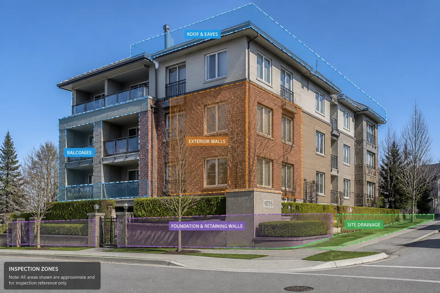
Frame corner perspectives showing two intersecting elevations simultaneously to verify wall junctions, trim wraps, and continuous siding runs.
Capture complete roofline-to-grade framing on every elevation to establish overall scale, story heights, and architectural offset zones.
Technical Trace: Connecting Elevation Views to Scope Verification
High-level elevation overviews serve as visual master keys when evaluating exterior scope quantities. When reviewing line items for siding detachment, window wrap replacement, or masonry tuckpointing, the scope reader references elevation overviews to verify total square footage, evaluate obstacle density, and confirm access equipment requirements.
“Without a comprehensive elevation overview that frames the complete wall plane from grade to roofline, isolated defect photographs lose their spatial validity during scope reconciliation.”
Elevation context photos also prevent inadvertent duplicate allowances across adjacent wall facets. For example, corner post assemblies and vertical expansion joints often span two elevations; establishing clean boundary markers during preliminary elevation capture prevents double-counting or uncoordinated split-scope calculations.
Standard Elevation Documentation Matrix
| Elevation Stage | Capture Objective | Field Scope Verification Value |
|---|---|---|
| Primary Elevation Overview | Full wide-angle view from grade to eaves showing complete front facade and address context. | Validates building identity, story height, fenestration layout, and overall structural perimeter. |
| Corner Junction Tie-In | Oblique angle capturing intersecting front and side planes at standard wall corners. | Confirms continuity of fascia, gutter runs, corner post trim, and material transition boundaries. |
| Elevation Zone Indexing | Segmented grid shots of large elevations dividing upper and lower levels or architectural bays. | Directly cross-references localized defect markers to designated square footage calculation zones. |

Field Inquiries & Observations
No comments yet. Be the first to leave a field observation or inquiry.
Submit a Field Note or Feedback
Share your site observation insights or questions regarding this methodology.