Key Takeaways & Protocol Essentials
- Always pair borescopic inspection images with wide-angle contextual reference markers on the outer wall surface.
- Record moisture meter pin-depth probes and infrared anomalies alongside physical boundary measurements.
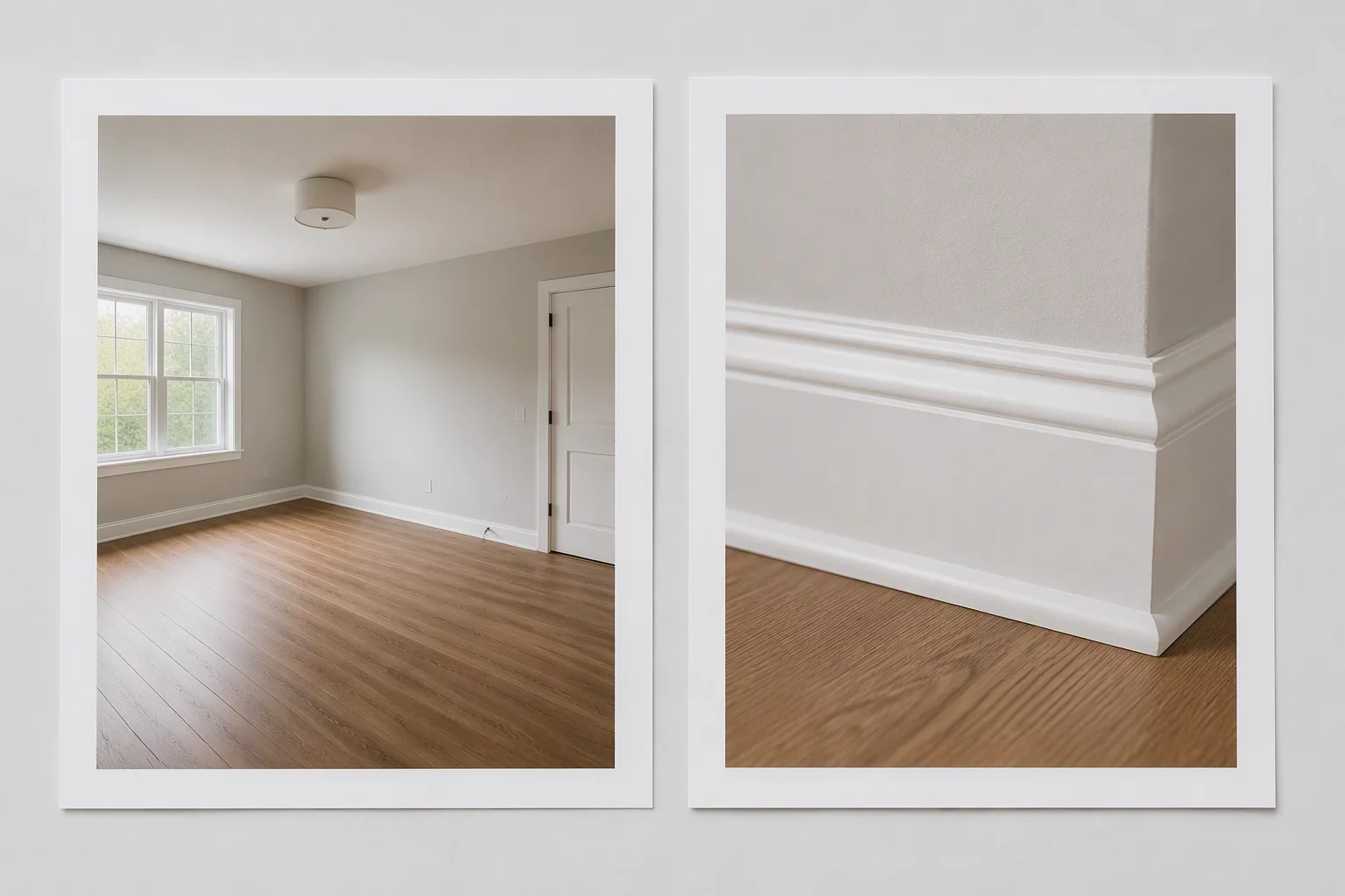
- Maintain sequential photographic logs before, during, and after removing baseboards or opening exploratory drywall cuts.
Establishing Strategic Access Points for Cavity Inspection
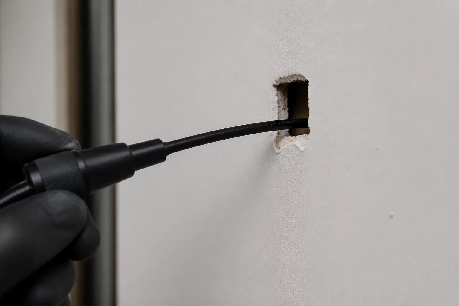
Capturing concealed structural compromise requires disciplined physical alignment before any interior wall board or subfloor surface is altered. Field specialists initiate documentation by photographing the intact wall assembly alongside a distinct reference datum such as an electrical receptacle or architectural molding. When inserting a borescopic camera probe through an existing outlet cutout or mechanical access opening, the exterior perspective shot establishes absolute spatial coordinates. This two-step sequence ensures every interior image matches a verified physical point on the inspection plan.
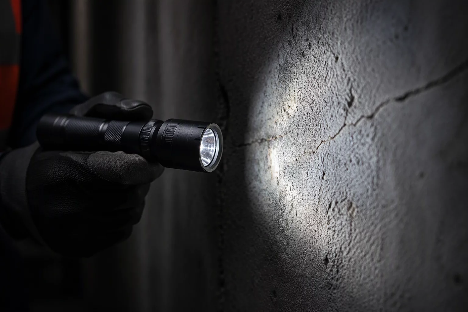
Concealed framing elements, damp fiberglass batts, and compromised sill plates frequently sit behind visually sound drywall surfaces. Using calibrated inspection probes paired with high-lumen auxiliary fiber optics reveals moisture migration paths that surface photography misses entirely. Documenting these hidden conditions establishes clear evidence trails that support precise repair scope decisions without relying on unverified assumptions.
Core Evidence Standards for Concealed Assemblies
Every cavity photograph must be indexed to an exterior layout grid or elevation coordinate to verify the exact wall stud bay inspected.
Fiber-optic probe insertion depths must be recorded with scaled sleeve markers to calculate structural sill proximity.
Infrared thermal gradients must always be corroborated by quantitative pin moisture readings documented in direct succession.
Corroborating Concealed Structural Defects
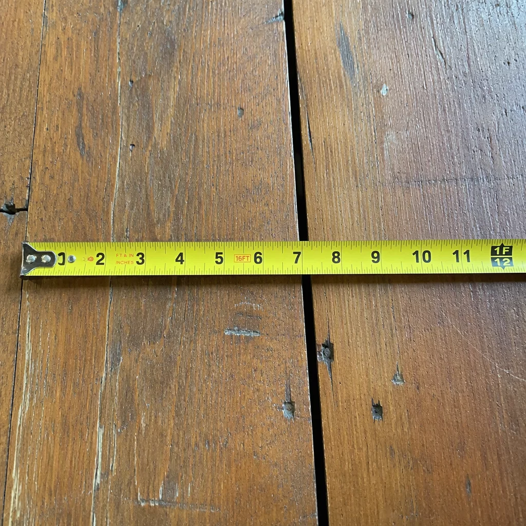
Hidden damage documentation succeeds when individual observations connect directly into a continuous evidence chain. When subfloor framing beneath tile displays suspected deflection or rot, capturing the underside from crawlspace access provides definitive proof that topside cosmetic patching would fail. The field note must catalog the exact joist number counting from the foundation stem wall, the measured span distance, and macro shots of wood fiber condition.
Concealed damage documentation is only as reliable as the physical datum connecting the unseen cavity to the visible floor plan.
Linking subfloor probe photos with adjacent wall cavity conditions creates an unambiguous technical narrative. Field technicians record structural member dimensions alongside calibrated gauge readings, allowing scope reviewers to evaluate whether selective framing sistering or full bay reconstruction represents the accurate repair scope documentation standard.
Non-Destructive vs Invasive Evidence Standards
| Inspection Technique | Photo Documentation Protocol | Scope Verification Output |
|---|---|---|
| Borescopic Probe | Internal cavity image with outer entry hole datum | Validates insulation wetness and stud condition |
| Thermal Infrared | Radiometric delta capture with ambient baseline | Defines perimeter boundary for moisture extraction |
| Exploratory Cut | Dimensioned square cut with depth scale and framing view | Proves sub-sheathing substrate deterioration |
Field Inquiries & Observations
Submit a Field Note or Feedback
Share your site observation insights or questions regarding this methodology.