Key Takeaways & Protocol Essentials
- Keep digital markings minimal and high-contrast, ensuring annotations highlight damage boundaries without obscuring underlying surface texture.
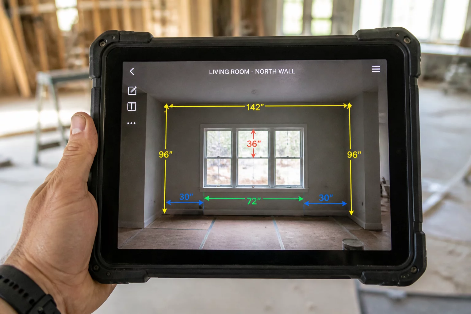
- Always pair directional arrows with exact dimensional callouts or physical reference scales captured in the same frame.
- Standardize callout abbreviations and terminology across all photos to match exact repair scope line-item descriptions.
Establishing Standardized Annotation Protocols
Visual documentation in property inspection demands precise clarity. Without standard markers, an adjuster or estimator reviewing raw photos from a desktop cannot distinguish between minor surface irregularities and severe structural compromises. Adding structured annotations bridges the physical site reality and the digital estimating environment, creating unambiguous evidentiary records.
When annotating field photos, every markup must serve a distinct purpose. Clean vector lines, boxed boundary perimeters, and contrasting text callouts direct attention to specific material transitions, waterlines, and detachment points. Applying consistent color coding—such as cyan for dimensional bounds and red for critical fracture points—streamlines cross-referencing during estimate and scope review.
Essential Field Markup Rules
Never place opaque solids, heavy brush strokes, or oversized callout boxes directly over the fracture or impact epicenter; place markers adjacent with thin leader lines.
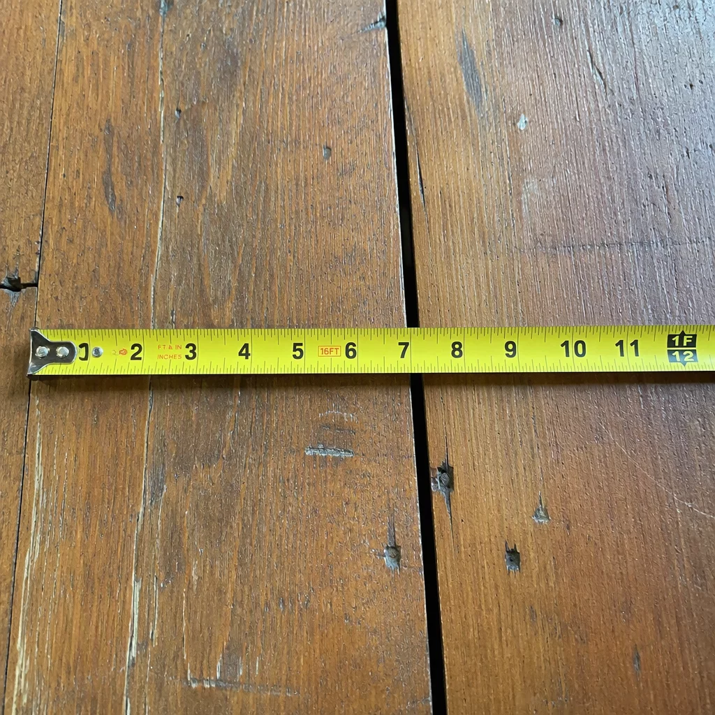
Anchor all dimension callouts to visible physical rulers, laser meter readings, or known structural elements to prevent scale distortion across wide-angle captures.
Tag every marked boundary with its corresponding repair action code, distinguishing between continuous replacement spans and isolated material detachments.
Contextual Traceability from Lens to Scope
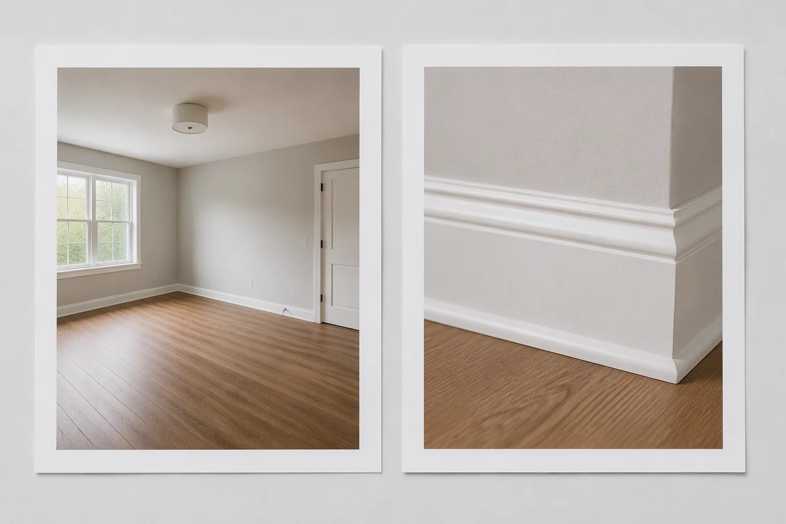
Integrating digital markup workflows into site capture procedures significantly accelerates estimate validation. When an estimator drafts repair lines in an Xactimate scope context, annotated photos provide immediate spatial verification for drywall cut lines, baseboard detachments, and paint transitions without requiring speculative field re-inspections.
“An unannotated damage photograph only proves an anomaly exists; a methodically marked photograph proves its exact extent, boundary, and required scope of repair.”
Systematic visual indexing establishes an unbroken evidentiary chain. By documenting the exact progression from wide-angle contextual overviews down to annotated close-up measurements, field specialists ensure that third-party auditors and property owners can verify every calculated square foot with complete confidence.
Annotation Specifications & Standard Field Legend
| Markup Element | Field Application | Documentation Standard |
|---|---|---|
| Directional Arrow (Leader) | Points to subtle hairline fractures, moisture capillary edges, or fastener pull-throughs | Single-pixel to 2px stroke, bright cyan or crimson, arrow head resting 5mm away from target |
| Boundary Polygon | Defines full perimeter of required material tear-out or continuous floor replacement | Dashed outline, 20% transparent fill maximum, corner vertices mapped to structural joints |
| Dimension Indicator | Specifies linear footage of baseboard or height of continuous water stain line | Dual-arrow dimension line paired with explicit numeric value and unit designation (e.g. 8'-6" AFF) |

Field Inquiries & Observations
No comments yet. Be the first to leave a field note or observation.
Submit a Field Note or Feedback
Share your site observation insights or questions regarding this methodology.