Key Takeaways & Protocol Essentials
- Blown fiberglass and loose cellulose settle unevenly across joist bays, rendering single-point visual tags inadequate for thermal boundary documentation.
- Conducting a disciplined estimate scope review demands graduated photographic probe depths referenced against structural ceiling zones.
- Linking physical attic depth data with explicit Xactimate scope context prevents contentious post-mitigation supplemental scope discrepancies.
Identifying Thermal Deficits in Blown-In Attic Insulation
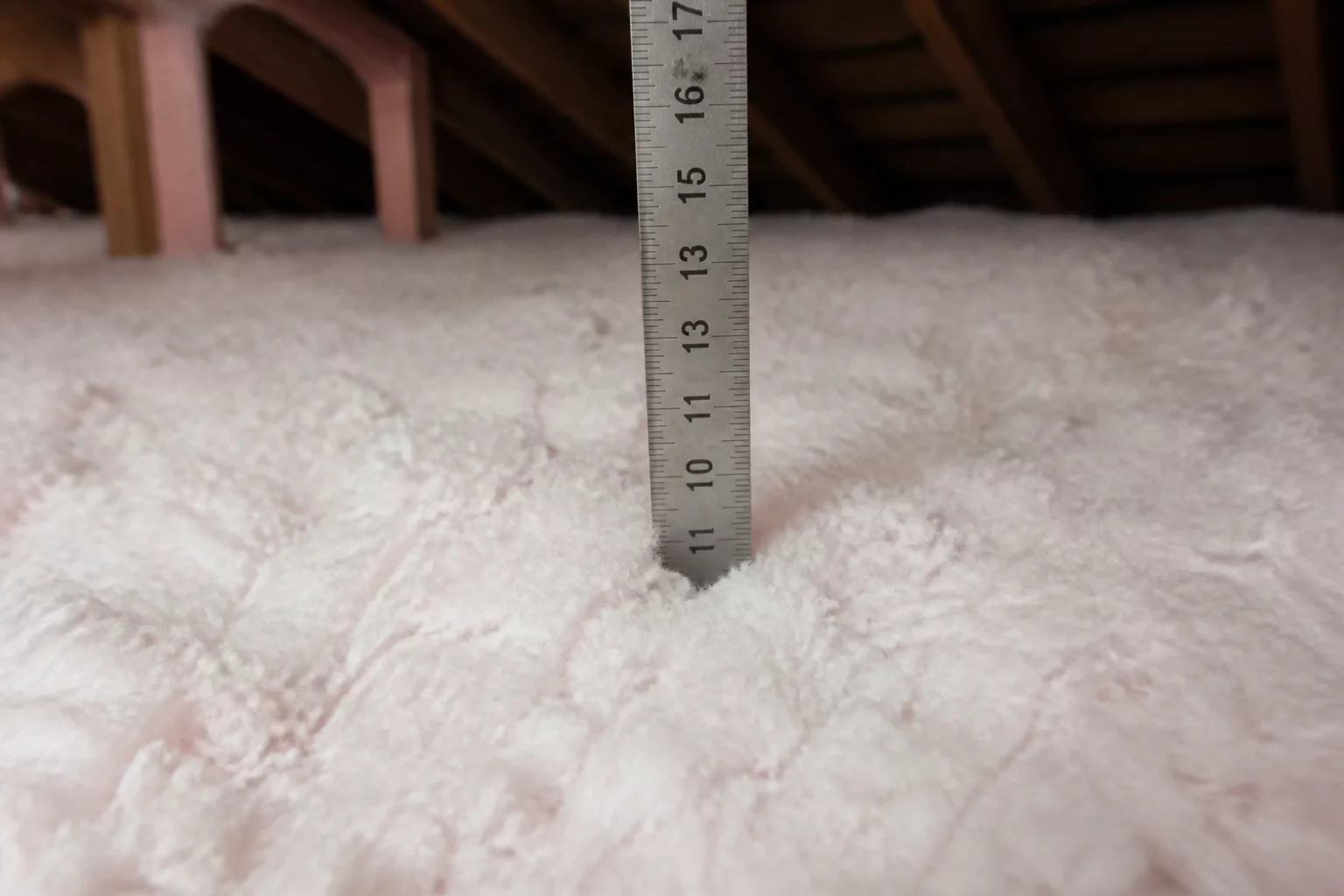
During structural damage reviews involving attic spaces, thermal boundary degradation frequently presents complex documentation challenges. In this field investigation, the preliminary file listed a uniform attic insulation depth of twelve inches across the entire 2,100 square foot ceiling plane. However, hands-on probe testing revealed significant depth variance ranging from under four inches along the exterior eaves to fourteen inches banked against central framing chases. Relying on an averaged general depth distorted the repair scope documentation, masking zones of complete thermal failure.
Loose-fill fiberglass and cellulose migrate and compress under the influence of historical soffit airflow, air filtration currents, and past mechanical traffic. By recording multi-point graduated ruler depths rather than relying on standard attic access tags, our team documented the genuine physical state of the ceiling envelope. This rigorous approach furnished the tangible evidence necessary for an objective estimate scope review, ensuring line-item accuracy prior to establishing final repair specifications.
Field Findings & Diagnostic Measurements
Calibrated metal depth gauges inserted into fifteen distinct bays documented a 48% depth deficit along the northern exterior boundary where wind washing occurred.
Localised condensation beneath uninsulated bath vent ducting compressed blown fibers into dense 3-inch slabs, permanently stripping away the engineered R-value.
Fallen cardboard vent chutes allowed incoming soffit air to strip insulation completely bare across four perimeter rafter bays, exposing upper drywall surfaces.
Scope Alignment and Xactimate Line Item Trace
Establishing clear Xactimate scope context requires linking physical depth measurements directly to itemized allowances. When blown-in insulation suffers localized compaction or contamination, standard full-attic removal items often fail to reflect actual salvageable boundaries. We structured the field notebook to isolate degraded sectors from unaffected zones, establishing precise square footage boundaries for both complete vacuum extraction and supplemental top-off capping.
“Accurate thermal boundary scoping relies on verified physical depth markers; without graduated photographic probes, line-item quantities represent guesswork rather than empirical field evidence.”
By mapping graduated ruler photos against a dimensioned attic floor layout, the field audit resolved ambiguities between replacement depth and code-mandated R-38 thermal thresholds. This structured evidence trail enabled all parties involved in the repair scope documentation workflow to verify why specific perimeter zones required complete extraction while central bays simply required a blown-in top cap.
Attic Zone Depth & Specification Matrix
| Attic Framing Zone | Measured Probe Depth | Scope Action & Code Target |
|---|---|---|
| Zone A (North Eaves / Soffit Perimeter) | 3.5 in. - Wind Washed / Compressed | Vacuum Extraction & R-38 Blown Infill with Baffles |
| Zone B (Central Attic Floor Area) | 11.5 in. - Undamaged / Minor Settling | R-11 Blown Loose-Fill Cap to Reach R-49 |
| Zone C (HVAC Platform & Walkway) | 4.0 in. - High Compression / Trampled | Batt Extraction & Rigid Perimeter Thermal Barrier |
Field Inquiries & Observations
No comments yet. Be the first to leave a field note or observation.
Submit a Field Note or Feedback
Share your site observation insights or questions regarding this methodology.